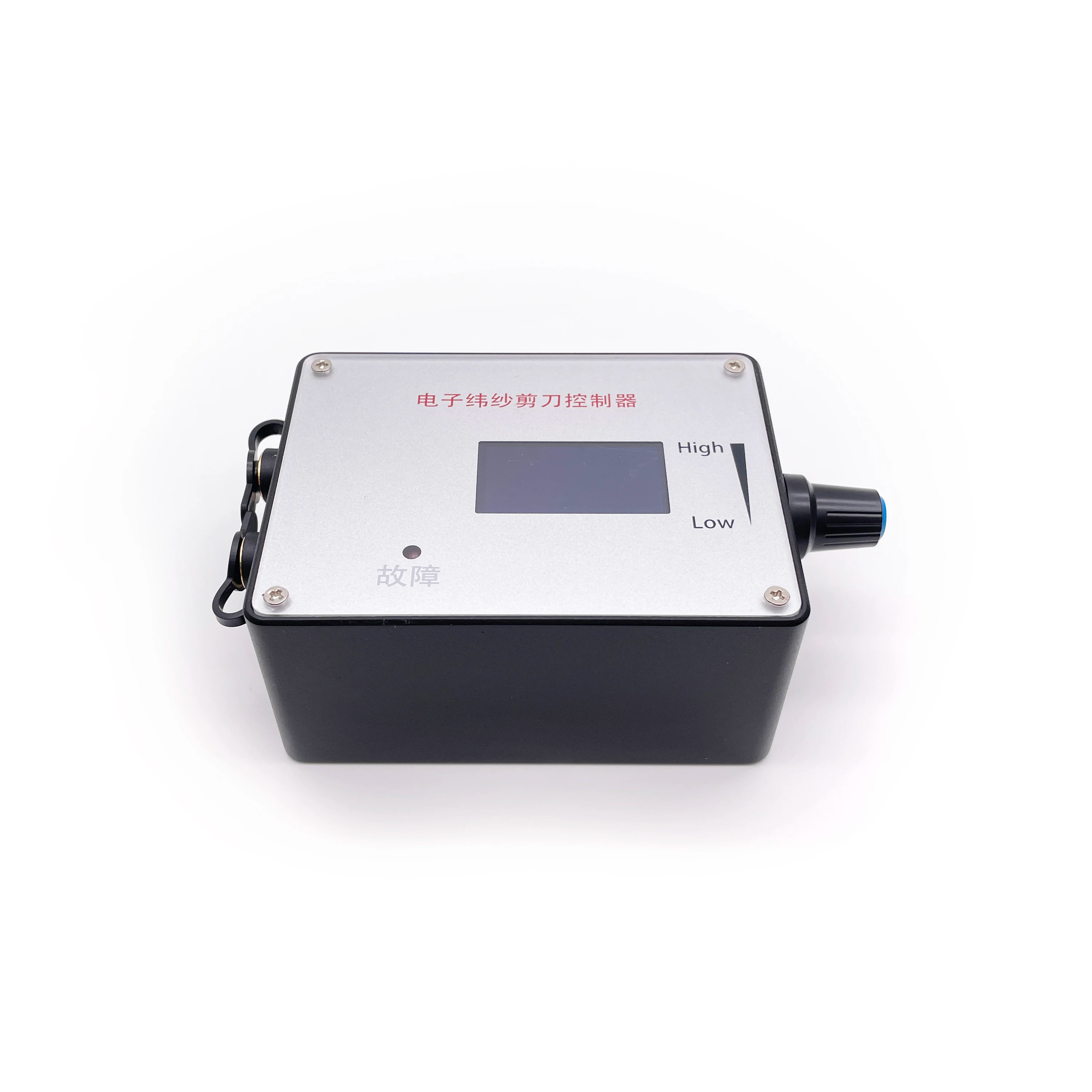
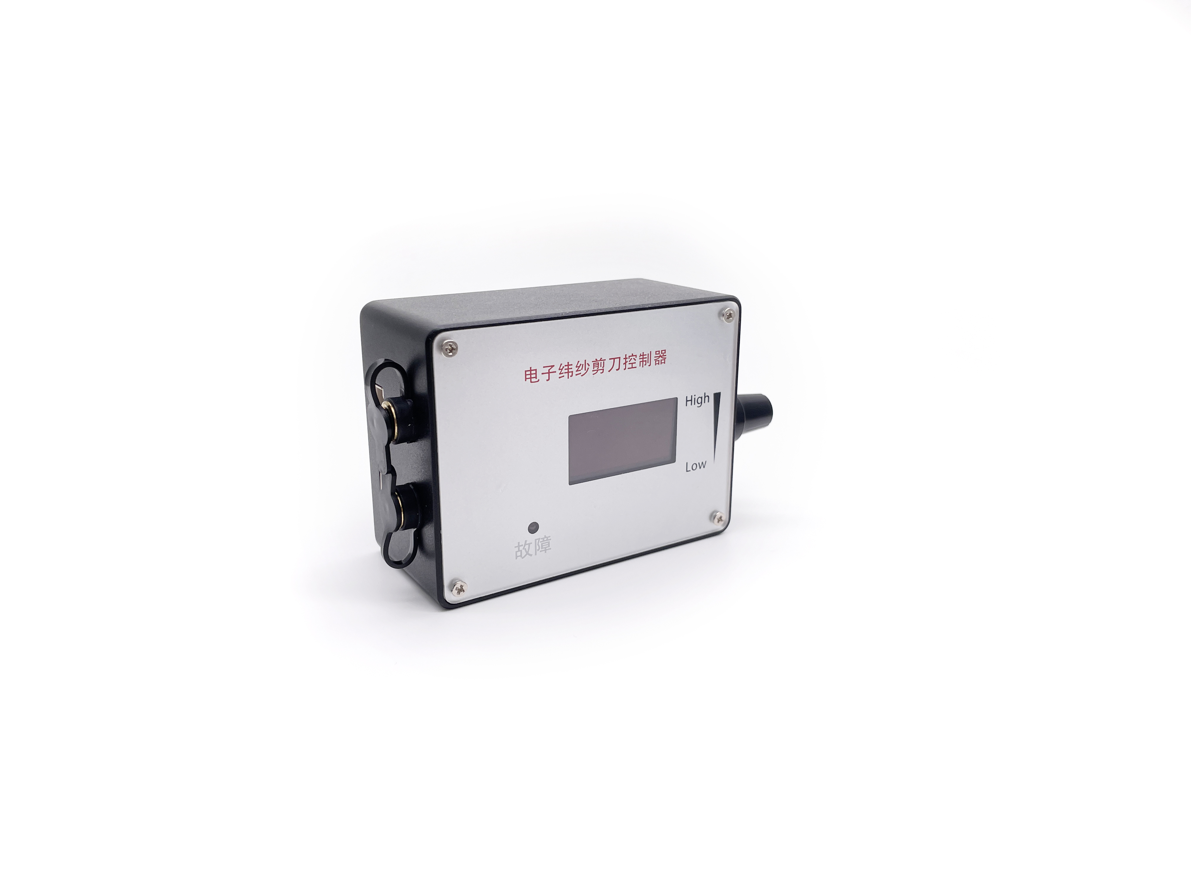
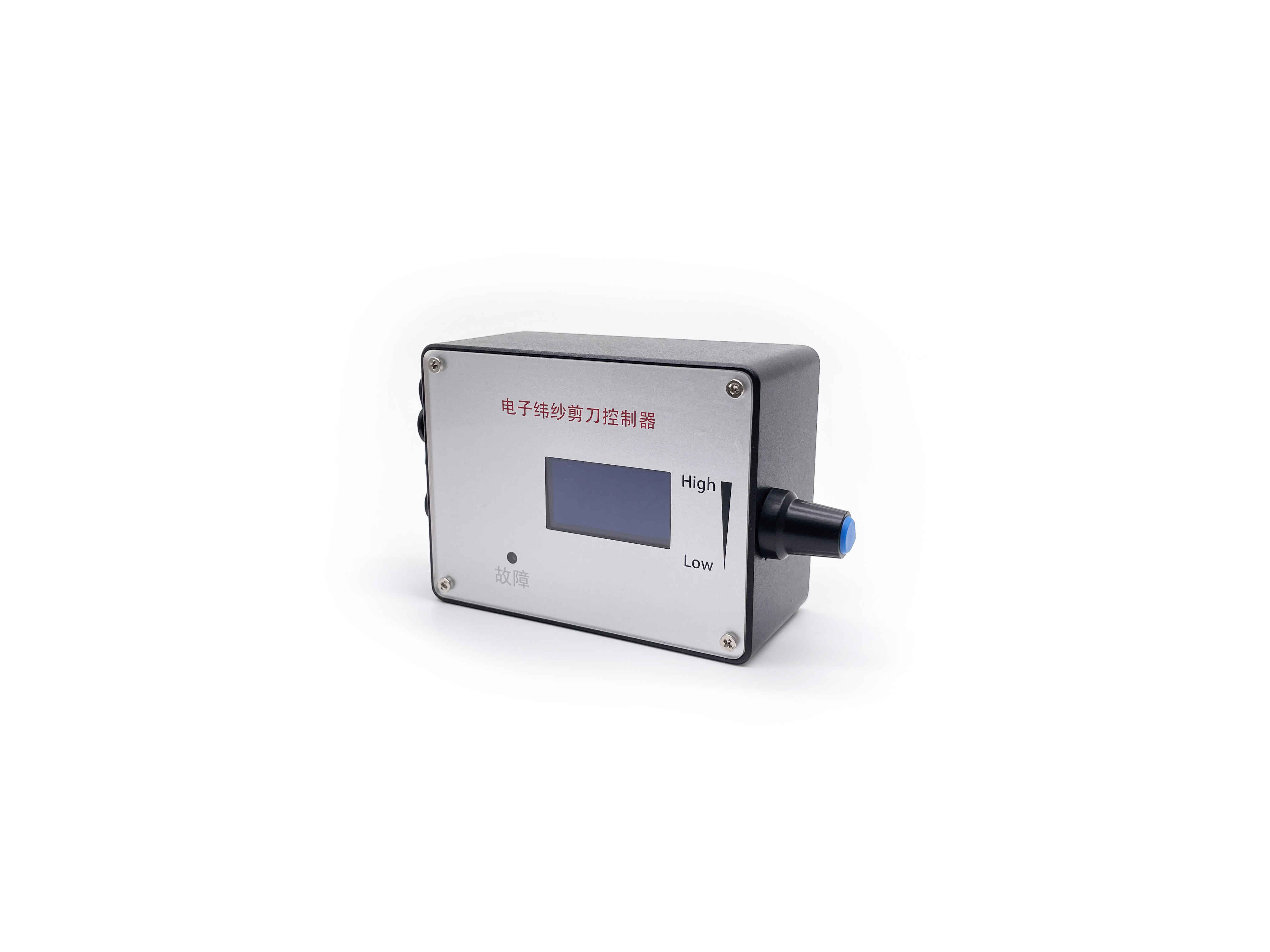
Rated Current: MAX 2A. (To control motors with higher current, connect the motor power line directly to the power supply, bypassing the governor.)
PWM Output Frequency: 0 - 100KHz
Analog Voltage Output: 0 - 5V
Operating Temperature: -10°C to 70°C
Storage Temperature: -30°C to 125°C
Driver Board Size: 60mm (Length) X 40mm (Width)
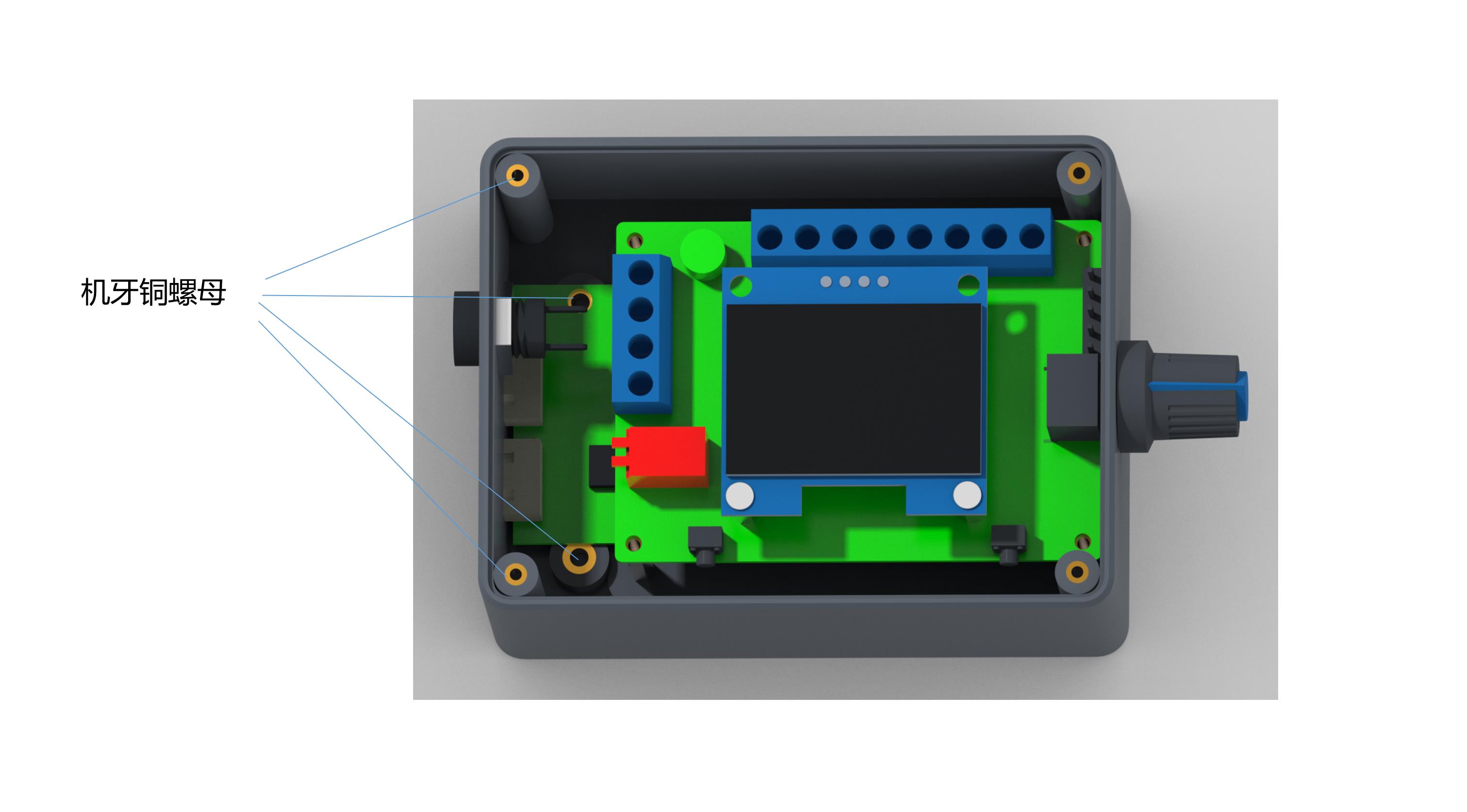
Governor Wiring & Internal Functions
1
Power Positive Input: Connects positive power supply for both governor and motor.
2
Power Negative Input: Connects negative power supply input.
3
Motor Power Positive Output: Dedicated positive output terminal for the motor.
4
Motor Power Negative Output: Dedicated negative output terminal for the motor.
5
Rotation Control (F/R): High/Low level output for positive and negative rotation control. High level: 5V, Low level: 0V. Controlled via touch switch 2. Default: High level.
6
Brake Control (BRA): High/Low level output for brake control. High level: 5V, Low level: 0V. Controlled via touch switch 1. Default at power-on: High level.
7
Analog Voltage Output: Range 0 - 5V. Designed for motors requiring analog voltage speed regulation.
8
PWM1 Reverse Output: Suitable for speed-regulated motors where speed is inversely proportional to the duty cycle.
9
PWM2 Forward Output: Suitable for speed-regulated motors where speed is directly proportional to the duty cycle.
10
Motor Feedback Signal Input (FG): Inputs the speed feedback signal from the motor.
Technical Notes:
• Outputs 7, 8, and 9 can be fine-tuned using the onboard potentiometer.
• FG/FG*3 & CW/CCW Jumper Settings: Adjust based on motor specifications. A jumper cap on the FG pin scales the feedback times by 3 (FG*3), while leaving it open registers a single time feedback (FG). For direction, adding a jumper cap configures default CCW startup; leaving it open sets it to CW.
Governor Parameter Settings Instructions
1
Frequency Setting
Press and hold touch switch 1 before powering on. Power on the board. Release the button once the screen displays "FEQ:20K". Touch switch 1 to decrease or switch 2 to increase. The factory default value is 20KHz.
2
Poles Number Setting
Hold down both touch switch 1 and switch 2 simultaneously, then power on the board. Release the buttons when the screen displays "Poles: 1 polarity". Use touch switch 1 to reduce or switch 2 to increase to match the motor's pole configuration. Factory default: 1 pole.
3
Feedback & Direction Settings
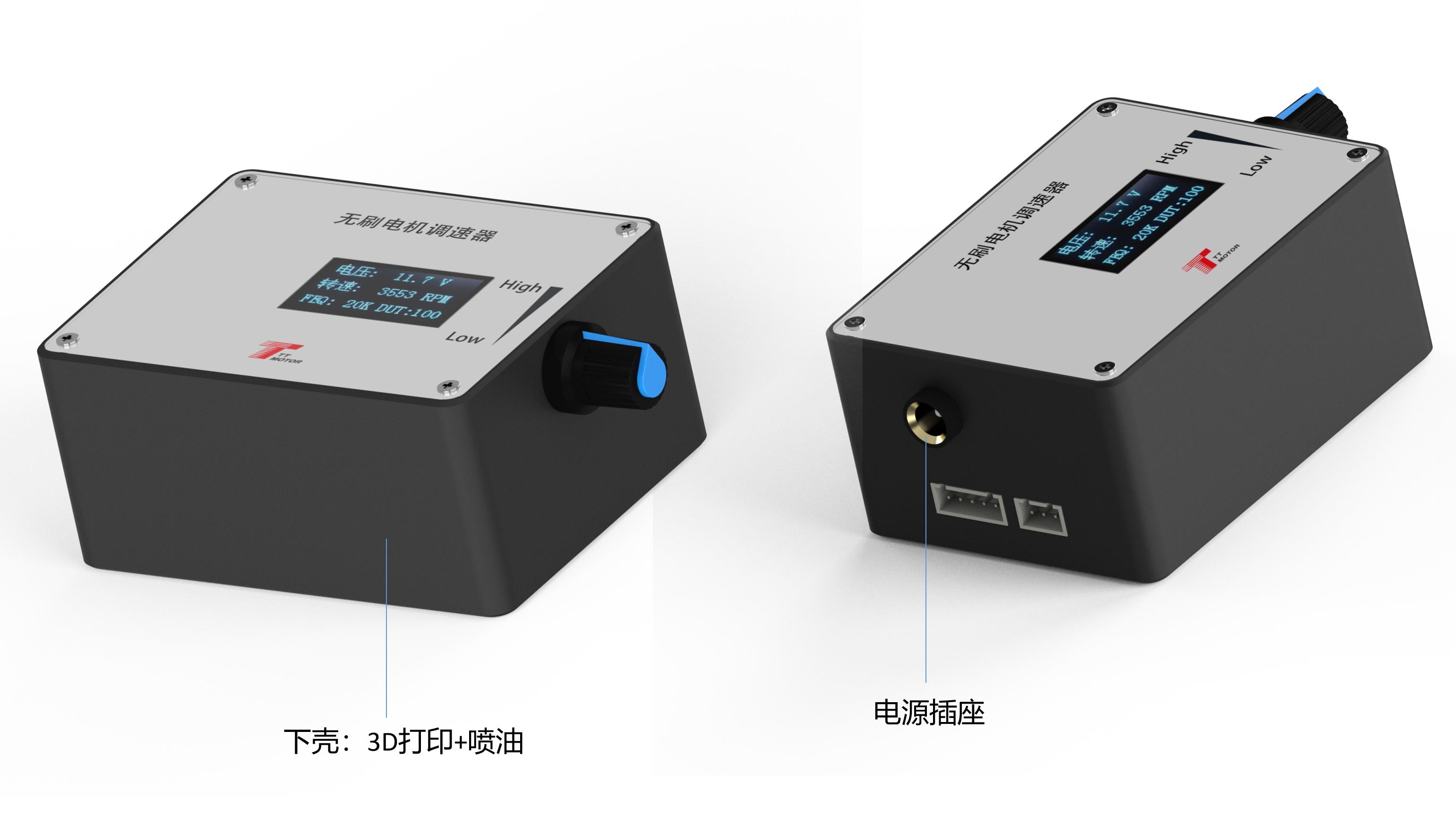
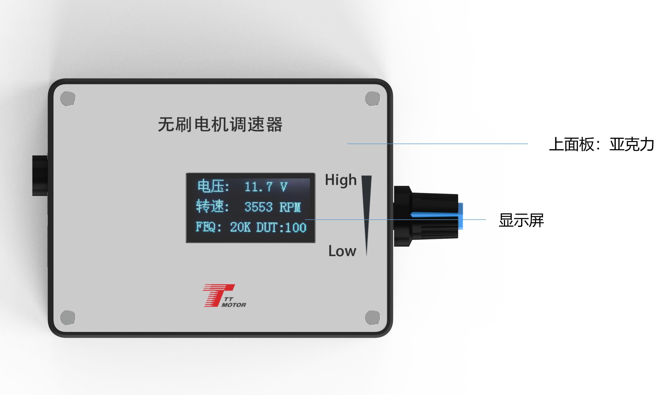
Adjust the FG/FG*3 pins for the feedback multiplier and the CW/CCW pins for the default motor startup rotation state (CCW with jumper cap, CW without). The main UI screen dynamically displays input voltage, speed, frequency, and duty cycle.
Critical Governor Precautions
1. **Wiring Safety:** Positive and negative inputs must be wired exactly to specifications. Reverse polarity connection will cause permanent board damage and burn the governor out.
2. **Compatibility:** The governor is strictly built to match motors matching the specified control interface standards.
3. **Voltage Restriction:** Ports 5 through 9 (⑤ to ⑨) must NOT receive inputs exceeding 5V under any operating circumstances.
Frequently Asked Questions (FAQ)
Q1: Can I run a motor that draws more than 2A of current?
A: Yes, but you must connect the motor's power line directly to the main power supply instead of routing it through the governor board to prevent overloading the device.
Q2: How do I change the default frequency setting?
A: Press and hold touch switch 1 before powering on, then turn on the system. Once the screen shows "FEQ:20K", release the button and use switch 1 to decrease or switch 2 to increase the frequency.
Q3: What happens if the power polarity is accidentally reversed?
A: The governor is not protected against reverse polarity input. Reversing the positive and negative connections will damage the internal circuitry. Always check connections carefully before powering up.
Q4: How do I configure the motor rotation direction on startup?
A: The default startup direction is managed by the CW/CCW pin configuration. By inserting a jumper cap on this pin, the initial state is configured to CCW. Leaving the cap off defaults the startup direction to CW.
Q5: What limits apply to the five signal ports (5-9)?
A: The high/low level, brake, analog voltage, and PWM output ports (numbered 5 to 9) cannot tolerate voltages above 5V. Connecting higher voltages will damage the control logic.