Choosing a Geared Drive Motor is not just a matter of comparing horsepower or price. The right unit must match the machine’s load, speed, duty cycle, and operating environment. A conveyor moving wet aggregate needs different protection and output torque than a packaging line indexing small cartons. Details matter. A poor match can mean excess heat, noisy operation, or avoidable maintenance.
W. Edwards Deming, an influential industrial quality expert, said, “A system must be managed. It will not manage itself.” That principle fits drive selection: a motor, gearbox, controller, and driven load work as one system. Buyers should check reduction ratio, starting torque, service factor, mounting position, enclosure rating, lubrication needs, and compatibility with variable-frequency drives. Then they should confirm the manufacturer’s ratings against the actual operating conditions, not just a catalog’s headline figures.
This Top 10 guide compares geared drive motors for common industrial applications, including conveyors, mixers, lifts, and machine tools. It considers performance, durability, efficiency, configuration options, and service support. A high efficiency rating is useful, but it cannot rescue an unsuitable ratio or an overlooked thermal limit. Rankings also have limits; plant conditions vary, and product availability changes. Use the list to narrow the field, then verify specifications with the manufacturer or a qualified drive engineer before purchase. The best choice is often the one that fits quietly, runs reliably, and is easy to maintain. Quite simple—until the real load arrives.
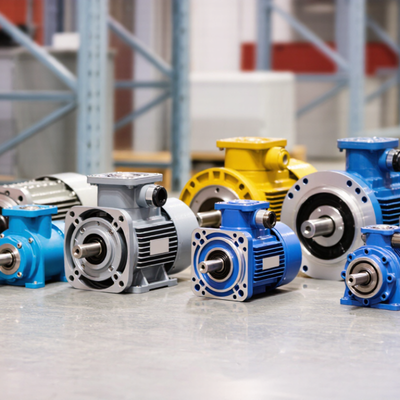
A geared drive motor combines an electric motor with a gearbox. The motor supplies rotation; gears reduce output speed and increase torque. In practice, a conveyor may need a slow, steady pull rather than a motor’s high-speed rotation. Gear ratios set that trade-off. Actual output also depends on efficiency, load, and operating conditions.
The assembly typically includes a motor, gear stages, shafts, bearings, seals, and lubricant. Spur and helical gears suit many general duties; planetary designs can deliver high torque in a compact package. Worm gears offer large reductions, though they may lose more energy as heat. Small losses add up.
The U.S. Department of Energy’s Improving Motor and Drive System Performance sourcebook estimates that motor-driven systems use about 68% of electricity in U.S. manufacturing. That figure covers motor systems broadly, not geared motors alone. Still, it shows why matching speed, torque, and load matters.
A gearbox chosen only by its ratio may run hot, waste energy, or wear prematurely. Check the duty cycle, mounting position, lubrication needs, and starting load. Real installations are rarely as tidy as a catalogue example.
A geared motor combines an electric motor with a reducer, which lowers speed and increases usable shaft torque. Inside the housing, gears transfer force while bearings support rotating shafts. Seals keep lubricant in and dust or moisture out. Small details matter. A leaking seal can shorten bearing life, while poor lubrication raises heat and wear.
Compare output torque and speed at the actual operating point, not only the motor’s rated power. Check the service factor, duty cycle, thermal limits, enclosure protection, and mounting position. IEC 60034-30-1 defines IE efficiency classes for motors, but that rating does not describe the complete geared unit. Reducer losses also depend on gear type, ratio, lubricant, and load. The distinction is easy to miss.
The International Energy Agency’s 2023 analysis estimates that motor-driven systems consume about 53% of global electricity. That figure makes efficiency more than a nameplate detail. Yet a high-efficiency motor may not deliver the best system performance if it is oversized or poorly matched to the load. For a conveyor starting with a full belt, verify starting torque and thermal duty; for a fan running steadily, compare efficiency near its normal load. Published ratings help, but field conditions can still expose gaps.
Industrial geared drive motors pair an electric motor with a reduction gear to deliver useful torque at a controlled speed. Spur gearmotors suit simple feeders and light conveyors, though their straight teeth can become noisy at higher speeds. Helical gearmotors run more smoothly, making them common on equipment that operates for long shifts. Parallel-shaft helical units fit long conveyor lines where space and steady torque matter.
Bevel gearmotors turn power through an angle, often 90 degrees, when layouts leave little room. Helical-bevel units offer a similar right-angle arrangement with smooth meshing. Worm gearmotors provide compact, high reductions for lifts and positioning systems, but heat and efficiency deserve attention. Helical-worm units balance compactness with smoother transmission. No option is automatically best.
Planetary gearmotors pack high torque into a small housing, useful in robotics and mobile machinery. Cycloidal gearmotors tolerate shock loads in demanding industrial drives, although vibration and maintenance still need checking. Shaft-mounted gearmotors attach directly to driven equipment, reducing the need for separate couplings. That saves space, but alignment and support still matter. In practice, compare load cycles, output speed, mounting position, and thermal limits before choosing. A catalog rating alone can mislead; real duty is messier.
| Rank | Geared Motor Type | Gear Arrangement | Typical Reduction Range | Key Characteristics | Common Industrial Applications |
|---|---|---|---|---|---|
| 1 | Inline Helical Geared Motor | Helical gears with input and output shafts in line | About 3:1–100:1, depending on stages | Efficient, smooth-running, and suitable for continuous duty; multistage designs provide higher reductions. | Conveyors, mixers, packaging machinery, and material-handling equipment |
| 2 | Parallel-Shaft Helical Geared Motor | Helical gear stages with parallel, offset shafts | About 3:1–200:1, depending on stages | Compact for its power capacity and well suited to applications requiring substantial torque at a low output speed. | Conveyor drives, bulk-material handling, and industrial process lines |
| 3 | Helical-Bevel Geared Motor | Helical stages combined with bevel gears for a right-angle output | About 5:1–200:1, depending on stages | Changes drive direction by 90 degrees while offering efficient power transmission and high output torque. | Conveyors, bucket elevators, agitators, and compact machine drives |
| 4 | Planetary Geared Motor | Central sun gear, surrounding planet gears, and an outer ring gear | About 3:1–100:1 per stage; higher ratios are available with multiple stages | High torque density, compact size, and good load distribution; often selected where space is limited. | Robotics, machine tools, indexing systems, and mobile industrial equipment |
| 5 | Worm Geared Motor | Worm screw driving a perpendicular worm wheel | About 5:1–100:1 in a single reduction stage | Provides a right-angle drive and large reduction in a compact housing; efficiency varies with ratio and design. | Small conveyors, gates, packaging equipment, and positioning mechanisms |
| 6 | Helical-Worm Geared Motor | Helical input stage combined with a worm reduction stage | About 10:1–300:1, depending on configuration | Combines the smooth operation of helical gearing with the high reduction capability of a worm stage. | Mixers, conveyor systems, and machinery requiring low output speeds |
| 7 | Cycloidal Geared Motor | Eccentric-driven cycloidal disc engaging a stationary pin ring | About 6:1–119:1 in a single stage; greater ratios use multiple stages | Designed for high reduction and shock-load tolerance; the mechanism has multiple load-sharing contact points. | Heavy-duty conveyors, wastewater equipment, and industrial drives exposed to variable loads |
| 8 | Spur Geared Motor | Parallel-shaft spur gears with straight teeth | Commonly about 3:1–10:1 per stage | Simple, economical, and straightforward to maintain; tooth engagement can be noisier than helical gearing. | Light-duty conveyors, feeders, small machine drives, and general-purpose equipment |
| 9 | Bevel Geared Motor | Bevel gears transmit power between intersecting shafts, commonly at 90 degrees | About 1:1–5:1 per bevel stage; additional stages increase reduction | Changes shaft direction efficiently and can be used in right-angle drive arrangements. | Compact right-angle drives, machine tools, and material-handling machinery |
| 10 | Hypoid Geared Motor | Hypoid spiral-bevel gears with offset, non-intersecting shafts | Commonly about 5:1–15:1 per stage, depending on design | Provides a right-angle drive with offset shafts and smooth, quiet operation; requires suitable lubrication. | Compact machine drives, packaging equipment, and selected conveyor applications |
Selecting a geared motor starts with the load, not the catalog. Record required output speed, continuous torque, peak starting torque, and operating hours. A conveyor carrying wet cartons needs different protection and starting capacity from a lightly loaded mixer. The U.S. Department of Energy’s Improving Motor and Drive System Performance: A Sourcebook for Industry reports that motor-driven systems account for about 70% of U.S. industrial electricity use. Efficient sizing matters, but oversizing can also waste energy and increase cost.
Match the gearbox ratio to the machine’s actual speed, then check service factor, duty cycle, mounting position, and ambient temperature. Helical gears often suit efficient, steady operation; worm gears can fit compact layouts, though heat and efficiency deserve attention. Confirm that the motor can handle starts per hour and brief overloads. One overlooked detail: frequent starts may raise temperature even when average load looks modest. A spreadsheet helps, but field conditions can disagree.
Tips: Measure the driven shaft speed and estimate the heaviest real load, not just the average. Check the gearbox’s thermal rating alongside its torque rating. Ask maintenance staff about washdown, dust, and available space. Leave room for uncertainty; load estimates are rarely perfect.
Geared drive motors need careful installation before they deliver reliable torque. Check the mounting surface for flatness, then align the motor and driven shaft to the manufacturer’s tolerances. Even slight misalignment can increase vibration and bearing loads. Confirm the gearbox ratio, service factor, and expected starting torque match the application. Keep cooling fins clear, and use the specified lubricant and fill level. Small errors matter.
Maintenance should focus on measurable changes, not just calendar intervals. The U.S. Department of Energy’s Improving Motor and Drive System Performance guide estimates that motor-driven systems use about 68% of electricity in U.S. manufacturing. Efficient operation is worth protecting. Record baseline vibration, housing temperature, noise, and oil condition after commissioning; compare later readings under similar loads. Metal particles or a rising temperature may signal wear or lubrication problems. A checklist helps, but it can still miss a slow change between inspections.
Safety begins before opening a coupling guard or servicing a reducer. Isolate and lock out all energy sources, verify zero energy, and prevent unexpected restart. OSHA’s control-of-hazardous-energy standard, 29 CFR 1910.147, requires documented energy-control procedures for covered servicing work. Use rated lifting points when handling heavy assemblies, and reinstall guards before operation. Never test a loose coupling by hand while energized. In practice, rushed adjustments are tempting; they are also where a sound procedure can break down.
It combines an electric motor with reduction gears to provide controlled speed and useful torque. The gear ratio shapes the output.
Parallel-shaft helical units often suit long lines with steady torque needs. Check the available mounting space and load cycle.
It offers compact construction and a high reduction ratio, useful in lifts or positioning systems. Heat and efficiency need attention. They matter.
Its compact housing can deliver high torque for robotics and mobile machinery. Confirm that its rating fits real operating loads.
Use a flat mounting surface and align the motor and driven shaft within specified tolerances. Check the gear ratio and starting torque. Small errors count.
Record vibration, housing temperature, noise, and lubricant condition after commissioning. Compare readings under similar loads. A slow change can be easy to miss.
They attach directly to driven equipment and can reduce the need for separate couplings. Support and alignment still matter.
Isolate and lock out energy sources, verify zero energy, and prevent unexpected restart. Use rated lifting points for heavy assemblies. Refit guards before operation. Rushing is tempting, but risky.
This article explains how a Geared Drive Motor combines an electric motor with a gearbox to deliver controlled speed and increased torque for industrial equipment. It introduces essential components, including the motor, gears, bearings, housing, and lubrication system, and outlines performance ratings such as power, speed, torque, efficiency, and duty cycle. It also surveys ten commonly used geared motor types, highlighting how their designs suit different operating conditions and mechanical requirements.
Readers will learn how to select a geared motor by considering the load, required output speed and torque, operating environment, mounting arrangement, and expected service life. The article also covers practical installation, routine inspection, lubrication, and maintenance, along with safety measures for handling and operating equipment. Together, these topics provide a useful foundation for choosing and caring for a geared motor in industrial applications.