What Is a Precision Gear Motor and How Does It Work?

Time:2026-09-08 Author:Oliver
0%

A Precision Gear Motor combines an electric motor with a gear train that controls speed, torque, and movement. It is used when ordinary motors cannot provide consistent positioning or reliable output under changing loads. You may find one inside robotic joints, conveyor systems, medical instruments, camera mechanisms, and automated valves.

Its operation begins with electrical energy entering the motor windings. The resulting magnetic field turns the rotor. That rotation then passes through several gears, which reduce speed and increase usable torque. The gear ratio determines how fast the output shaft moves. It also affects starting force, noise, efficiency, and mechanical response. A compact planetary gearbox, for example, can deliver high torque while fitting inside a small housing.

Small details matter. Incorrect alignment may create vibration, heat, or premature tooth wear. Excessive load can damage bearings, even when the motor still runs. Engineers usually check rated torque, stall torque, backlash, voltage, duty cycle, and shaft tolerance before selecting a model. Manufacturer test data is valuable, but real operating conditions deserve equal attention. No motor is ideal. Temperature, lubrication, and assembly quality can change performance significantly.

This guide explains what a Precision Gear Motor is and how it works in practical terms. It connects basic electromagnetic principles with real mechanical behavior. Readers will learn how gears modify motion, why precision matters, and which specifications influence long-term reliability. Some applications demand extreme accuracy, while others simply need stable, repeatable rotation. Choosing correctly requires more than comparing catalog numbers.
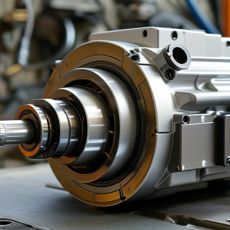
What Is a Precision Gear Motor and How Does It Work?

Precision Gear Motors: Definition, Purpose, and Core Characteristics

A precision gear motor combines an electric motor with a gear train designed to deliver controlled motion. Unlike a standard motor, it trades some speed for higher torque, repeatability, and positioning accuracy. Its purpose is practical: move a load smoothly, hold a position, and respond predictably under changing resistance. Typical applications include robotic joints, medical instruments, inspection equipment, and automated valves. Small movements matter.

Inside, electrical energy creates rotation in the motor. The gear train then adjusts that rotation through selected ratios. A reduction ratio lowers output speed while increasing usable torque, although efficiency losses remain. Precision depends on more than gears. Backlash, shaft alignment, bearing quality, temperature, and load inertia all influence final movement. In a real assembly, I would check these factors together rather than trust a catalog accuracy figure. That figure may describe ideal testing, not your operating conditions. Loads change.

Core characteristics include low backlash, stable torque, modest vibration, and consistent output over many cycles. Some designs use feedback sensors to correct position errors, while others rely on careful mechanical calibration. The right choice depends on duty cycle, load profile, allowable noise, and required lifetime. A motor that is precise at no load may behave differently under a heavy, reversing load. This is where selection can become imperfect. Testing with the actual gearbox, controller, and mounting structure often reveals errors that specifications cannot show.

Key Components and How They Work Together

What Is a Precision Gear Motor and How Does It Work?

A precision gear motor combines an electric motor with a reduction gearbox. The motor creates rotation, while the gearbox controls speed and increases usable torque. Inside, several gears transfer motion through carefully matched teeth. Their ratios determine how fast the output shaft turns. Lower speed often means stronger turning force.

The motor’s rotor spins inside a magnetic field produced by the stator. This rotation passes through a pinion gear and then through larger gears. Each gear reduces speed and changes torque. Bearings support the shafts and limit unwanted movement. A rigid housing keeps the gear centers aligned. Even a small alignment error can create noise, heat, and uneven wear.

An encoder can measure shaft position and speed. Its feedback allows a controller to correct motion during operation. For example, a conveyor may stop within a narrow distance instead of drifting forward. Lubricant reduces friction between the gear teeth, but too much lubricant can also increase resistance. Temperature, load, and installation accuracy affect real performance. The calculation may look perfect on paper. Field conditions are less tidy. Technicians should check backlash, vibration, and mounting bolts during testing. These details often reveal problems before the gearbox fails.

What Is a Precision Gear Motor and How Does It Work?

A precision gear motor combines an electric motor, reduction gears, bearings, housing, and often an encoder. The motor produces rotational speed and torque, while the gearbox reduces speed and increases usable output torque. The values below are engineering calculations for a 24 V motor producing 0.08 N·m of motor torque, using representative gearbox efficiencies and no brand-specific data.

The motor and gearbox work together through the relationship: output torque = motor torque × reduction ratio × gearbox efficiency. Higher reduction ratios generally increase torque, but they also reduce output speed and introduce greater mechanical losses. Bearings support the rotating shafts, the housing maintains alignment, and an encoder can provide position or speed feedback for closed-loop precision control.

How Torque, Speed, and Motion Are Controlled

A precision gear motor combines an electric motor with a reduction gearbox. The gearbox trades speed for usable torque. A high-speed motor may rotate at 3,000 rpm, while the output shaft turns at 60 rpm through a 50:1 ratio.

Torque follows a practical relationship: T = 9550P/n, where T is torque, P is power in kilowatts, and n is speed in rpm. Gear reduction increases output torque, but friction reduces the final result. A gearbox with 90% efficiency delivers less torque than the ideal calculation. Small errors matter. Thermal expansion, backlash, and lubrication can shift positioning accuracy during long operating cycles.

Motion control depends on more than the gear ratio. Encoders measure shaft position, while controllers adjust current, speed, and acceleration. A conveyor may move 100 millimeters, pause, and repeat within a narrow tolerance. According to the U.S. Department of Energy’s Better Plants guidance, motor-driven systems consume about 70% of industrial electricity. Efficient control therefore affects both precision and operating cost. The International Energy Agency has also reported that electric motor systems use roughly half of global electricity. That figure is broad, but it shows the scale of the problem. In practice, engineers should test the real load, not trust catalog calculations alone. That is where many designs become less perfect.

What Is a Precision Gear Motor and How Does It Work? - How Torque, Speed, and Motion Are Controlled
Control Dimension What It Means Representative Data How It Is Controlled or Calculated
Motor Type The electrical motor converts electrical energy into rotary motion. Common types: brushed DC, brushless DC, and stepper motors. A motor driver regulates voltage, current, commutation, or phase current according to the selected motor type.
Gear Ratio The ratio between the input speed and the output speed of the gearbox. Typical compact precision gearboxes: approximately 3:1 to 100:1, depending on the design. Output speed is approximately: nout = nmotor ÷ i, where i is the gear ratio.
Output Speed The rotational speed delivered by the gearbox output shaft. Example: a 3,000 rpm motor with a 30:1 gearbox produces about 100 rpm before load-related losses. Speed is adjusted by changing motor voltage, PWM duty cycle, commutation frequency, or commanded step frequency.
Output Torque The twisting force available at the gearbox output shaft. A small precision gear motor may provide output torque from a fraction of 1 N·m to several N·m, depending on size and thermal limits. Approximate calculation: Tout = Tmotor × i × η, where η is gearbox efficiency.
Gearbox Efficiency The percentage of input mechanical power transferred to the output shaft. Typical efficiency can range from about 60% to over 95%, depending on gear type, ratio, lubrication, and load. Efficiency decreases power loss and heat generation; higher ratios and multiple stages generally increase losses.
Backlash The angular clearance between mating gear teeth, observed when the output direction reverses. Precision gearboxes may specify backlash from below 1 arc-minute to several arc-minutes; actual values depend on construction and preload. Reduced through accurate tooth profiles, controlled clearances, preloaded bearings, and low-compliance mechanical structures.
Position Feedback The measurement used to determine the actual shaft position or speed. Encoders may provide hundreds to thousands of counts per revolution; effective output resolution also depends on gear ratio and signal processing. A controller compares commanded position with measured position and corrects the motor current or speed.
Motion Control The method used to regulate acceleration, velocity, position, and holding torque. Common modes: open-loop, closed-loop speed control, position control, and torque control. PID control is frequently used: proportional, integral, and derivative terms respond to tracking error.
Speed Regulation The ability to maintain a target speed when load or supply conditions change. Closed-loop systems generally regulate speed more accurately than open-loop systems, although performance depends on tuning and feedback quality. The controller increases or decreases motor current and drive command based on the difference between target and measured speed.
Torque–Speed Trade-Off Motor torque usually decreases as speed rises, especially near the motor's maximum operating speed. At a fixed voltage, a DC motor typically delivers its highest torque near zero speed and its highest speed near no load. The gearbox trades speed for torque; increasing the reduction ratio raises torque but lowers output speed.
Thermal Capacity The amount of heat the motor and gearbox can dissipate during continuous operation. Continuous torque is normally lower than short-term or peak torque because winding and gear temperatures must remain within rated limits. Duty cycle, ambient temperature, mounting method, current limit, and cooling determine safe continuous operation.
Mechanical Accuracy The ability of the output shaft to achieve repeatable angular motion under a specified load. Accuracy is affected by backlash, bearing runout, shaft elasticity, gear tooth errors, encoder resolution, and controller tuning. Precision is improved by minimizing mechanical clearance, using rigid couplings, calibrating feedback, and applying suitable control gains.
Power Relationship Mechanical power links torque and rotational speed. For torque in N·m and speed in rpm: P(kW) = T × n ÷ 9,549. A larger gear ratio can increase output torque, but available output power remains limited by motor power, gearbox efficiency, and thermal capacity.
Engineering note: The representative values above are general design ranges rather than universal ratings. Actual performance depends on motor size, gear geometry, reduction ratio, lubrication, operating temperature, load profile, feedback device, and controller settings.

Types of Precision Gear Motors and Their Applications

A precision gear motor combines an electric motor with a gearbox that controls speed, torque, and movement accuracy. The motor creates rotation. Gear teeth then reduce speed and increase usable torque. Bearings, shaft alignment, and backlash determine how accurately the output responds.

Planetary gear motors offer high torque density and low backlash. They suit robotic joints, conveyor positioning, and automated assembly tools. Harmonic gear motors provide very high reduction ratios in compact housings. They are common in collaborative robots, camera systems, and medical positioning equipment. Cycloidal gear motors tolerate shock loads and maintain steady motion. They fit welding robots, material-handling equipment, and heavy industrial actuators. Worm gear motors are quieter and economical, but efficiency can be lower.

Applications continue to expand with factory automation. The International Federation of Robotics reported 541,302 industrial robot installations worldwide in 2023. This scale increases demand for controlled motion and repeatable positioning. The International Energy Agency also identifies motor systems as major industrial electricity users, making efficiency important during continuous operation. A high reduction ratio alone does not guarantee precision. I have found that thermal growth, lubrication, and mounting stiffness can change real-world accuracy. Specifications may look perfect on paper. Testing under actual loads remains essential.

For medical devices, engineers often prioritize smooth starts and minimal vibration. Aerospace mechanisms demand low weight and dependable performance. Packaging machines need rapid cycling and predictable stopping. The best gear motor depends on load, duty cycle, noise limits, environment, and required backlash—not simply rated torque.

Factors for Selecting the Right Precision Gear Motor

A precision gear motor combines an electric motor with a gear train to deliver controlled speed and torque. Its value appears in robotic joints, conveyors, medical equipment, and automated positioning systems.

The International Federation of Robotics reported 541,302 industrial robots installed worldwide in 2023. That scale makes accurate motor selection increasingly important.

Start with the load profile, not the catalog headline. Calculate continuous torque, peak torque, output speed, acceleration, and reflected inertia. A higher gear ratio is not automatically better. It can improve torque while reducing speed and increasing backlash.

For positioning systems, specify allowable backlash, repeatability, and torsional stiffness. For continuous machinery, prioritize efficiency, thermal capacity, and service life.

The U.S. Department of Energy estimates motor systems consume about 69% of electricity in American manufacturing. Small efficiency losses can become expensive over long operating hours.

Check the duty cycle carefully. Intermittent operation may tolerate higher peak loads, but constant cycling demands better cooling and bearing capacity. Match the motor voltage, controller, encoder, mounting pattern, and environmental protection rating.

ISO 281 calculations can support bearing-life estimates, but real alignment and lubrication still matter. One practical mistake is trusting calculated life too much. Dust, vibration, and poor installation can shorten it sharply.

Test the complete assembly under realistic load conditions.

The specification may look perfect on paper. Reality is less tidy.

FAQS

: What is a precision gear motor?

: It combines an electric motor with gears for controlled, repeatable movement. Small movements matter.

Why use a gear reduction system?

Gear reduction lowers output speed and increases usable torque. Friction reduces the ideal result.

How does a reduction ratio affect motion?

A 50:1 ratio can reduce 3,000 rpm to about 60 rpm. The output moves slower.

How is output torque estimated?

Engineers can use T = 9550P/n. T means torque, P means power, and n means speed. Actual torque is lower when efficiency losses occur.

What affects positioning accuracy?

Backlash, shaft alignment, bearing quality, temperature, and load inertia all matter. Mounting errors matter too.

Can a motor stay precise under heavy loads?

Not always. A motor may perform well without load but shift during heavy reversals. Real testing is necessary.

Do feedback sensors improve motion control?

Encoders measure shaft position and help controllers correct movement errors. Mechanical calibration can also work.

Where are precision gear motors commonly used?

They support robotic joints, medical instruments, inspection equipment, and automated valves. They handle small, controlled movements.

What should engineers check before selecting one?

Check duty cycle, load profile, noise limits, lifetime, speed, torque, and mounting conditions. Catalog accuracy may not match real operation.

How can testing reveal hidden problems?

Test the complete motor, gearbox, controller, load, and mounting structure together. Specifications can miss vibration, heat, and reversing errors.

Conclusion

A Precision Gear Motor is an integrated drive system designed to deliver controlled torque, speed, and motion with high accuracy. It combines an electric motor with a gear mechanism that adjusts the motor’s output to meet the demands of a specific application. Key components may include the motor, gears, shafts, bearings, housing, and feedback or control elements. Working together, these parts reduce speed, increase usable torque, and transmit motion smoothly while limiting backlash, vibration, and positioning errors.

Precision gear motors are used in robotics, automation equipment, medical devices, inspection systems, and other applications that require reliable movement. Different designs, such as planetary, spur, worm, or harmonic gear systems, provide distinct advantages in efficiency, compactness, load capacity, and precision. Selecting the right motor requires evaluating operating speed, required torque, positioning accuracy, duty cycle, available space, noise level, environmental conditions, and control compatibility. A proper match helps ensure stable performance, long service life, and efficient energy use.

Oliver

Oliver

Oliver is a seasoned marketing professional with a wealth of expertise in driving brand awareness and engagement. With a deep understanding of our company's product offerings, he consistently delivers high-quality content that enriches our professional blog. His insights not only shed light on......